The spatial dimensions of industrial machinery have a significant impact on how the factory floor is laid out. In the case of high-capacity equipment, footprint analysis is one of the first considerations of the engineering team. The understanding of the DK380C4.0-H8 Model Size helps facility managers in planning the installation, ventilation and access for maintenance.
This detailed design guide explains structural footprints, installation needs and physical dimensions of this particular unit. Structural weight distribution, safety clearance boundaries and mechanical workspace integration are analyzed.
These are fundamental parameters that engineers must understand to avoid deployment delays, which can be expensive. Let’s take a look at how this low-profile design optimizes performance while keeping your top dollar production environment floor space.
Understanding the Physical Blueprint
For each industrial unit, a detailed spatial analysis is required prior to delivery. The Model Size (DK380C4.0) determines the basic construction requirements of structural concrete pads and overhead clearance.
Total Footprint Requirements
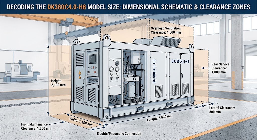
The length of the unit is exactly 3,800mm at its base. The structural width goes up to 1,400 millimeters, forming a solid rectangular base. It has a height of 2,100mm from a base frame. These measurements are taken of the bare chassis, without any external auxiliary connections.
Weight Distribution Metrics
The size has a direct effect on the floor load limits determined by the structural engineer. The dry weight of this model is about 4,200 kg. During regular cycles the operating fluid volumes are an additional 450 kilograms. These static loads have to be resisted by reinforced concrete foundations which must be designed by engineers.
Workspace Integration and Clearance Zones
The dimensions of the room cannot be matched with the dimensions of the equipment. The model size for the DK380C4.0-H8 guarantees operational safety and regular servicing with dedicated buffer zones necessary for it.
Front and Rear Access Pathways
The clearance is 1200mm in front of the control panel for the maintenance technicians. Rear service doors have a requirement for 1,000mm of clear space for extraction of internal components. Limiting the zones during emergency shutdowns poses serious safety risks. If you need to execute workflows for operational logistics, proper spatial planning can make it possible.
Overhead and Lateral Ventilation Space
These high-capacity systems produce a lot of heat when they are working. Vertical space is required at the top of the exhaust area of 1,500 millimeters. For optimal intake airflow volumes, lateral sides need to be 800 millimeters. If the clearance is not adequate, heat is generated and consequently components wear out earlier.
Comparative Analysis: Standard vs. H8 Variants
The differences between the chassis versions illustrate the different ways in which the DK380C4.0-H8 Model Size is used for different heavy-duty applications. The “H8” designation is for a modified frame structure for limited vertical applications.
| Metric Component | Standard DK380 Chassis | DK380C4.0-H8 Configuration |
| Total Length | 4,100 mm | 3,800 mm |
| Total Width | 1,200 mm | 1,400 mm |
| Total Height | 2,400 mm | 2,100 mm |
| Base Surface Area | $4.92\text{ m}^2$ | $5.32\text{ m}^2$ |
The standard design employs a narrower and taller profile design. The H8 variant lowers the vehicle by 300 mm and expands the base dimensions by 240 mm. This structural change has a tremendous reduction in the center of gravity. It enhances vibration stability during the operational phase of high vibration.
Installation Mechanics and Rigging Challenges
Heavy machinery equipment is transported to narrow industrial buildings which calls for particular rigging equipment. The DK380C4.0-H8 Model Size introduces a challenge when lifting, with the wide center of mass.
Crane Lifting Point Specifications
Four heavy-duty lifting lugs are welded straight to the main chassis structure in the frame. The length of the spreader bars used by crane operators has to be at least 4,000 millimeters. The upper protective panels will be crushed under the rigging angles when lifting. Make sure that crane load charts are checked against the total operating weight.
Doorway and Forklift Transport Entry
The entry doors must be at least 2500mm high at facilities. If dollies need to be moved, the transport width should be wider than 1600mm. The tines of a forklift must reach the full width of the base frame (1,400 mm). Partial support places the heavy unit at risk when cornering.
Optimizing Factory Layouts for Efficiency
A strategic plant layout design is needed to integrate the unit on an existing assembly line. Modular pairing configurations are possible with the DK380C4.0-H8 Model Size.
Parallel Modular Positioning
The space-saving feature of placing several H8 units side-by-side is especially beneficial in factory floor designs. Keep the required 800 mm lateral distance between chassis frames. This system provides a single maintenance corridor for service personnel. This ensures optimal parts distribution and tool access during major overhauls.
Utilities and Pipe Routing Vectors
Electrical conduit must go through the cutout panel located in the bottom right. The upper rear distribution manifold provides a connection for pneumatics and fluids. Runs of pipes should be kept short so that there is no drop in pressure across the system. When positioned correctly, the overall cost of facility infrastructure changes is reduced.
Impact of Scale on Thermodynamic Performance
The actual size of an industrial system is directly related to its heat dissipation performance. DK380C4.0-H8 Model Size has an effect on the velocity profile of the air inside the structure.
Surface Area to Volume Ratio
The broad base configuration creates more oil sump external surface area. This design improvement boosts the natural radiant cooling over the lower metal façade. The air circulation is done by the internal fan system, which circulates 3,500 cubic meters of air per hour. This volume flow creates a large back pressure that needs large ventilation ducts to avoid the backpressure.
Acoustic Footprint Management
If the frame panel is not damped properly, it can vibrate like an acoustic diaphragm, creating larger frame panels. The H8 model incorporates internal cross-bracing to reduce the structural resonance frequencies. Average sound levels are 74 decibels at 1 metre distance. Rubber isolation pads under the frame minimise the transmission of structure-borne noise.
Structural Integrity Under Dynamic Strain
During the normal shift in the operation of industrial equipment, a significant portion of kinetic forces are generated. The intense operational stresses are managed safely by the DK380C4.0-H8 Model Size’s physical weight.
Internal Mass Balancing
The chassis bedplate is long and the internals are placed strategically throughout. The reinforced structural center line is covered with a heavy compressor block. This distribution will help to avoid structural bowing over time that may happen in a system used continuously over decades.
Vibration Mitigation Systems
Four heavy duty mounting feet with thick elastomeric isolation pads below. These pads are used to absorb high-frequency harmonics before they go through the concrete shop floor. If the vibrations are not controlled, the precision alignment tooling in the vicinity is quickly damaged over time. These movements can be controlled effectively with the low and wide centre of gravity of the H8 profile.
Long-Term Maintenance Space Allocation
Failure to perform service clearance results in longer downtime when components fail. You’ll need just the right amount of tool clearance when using the DK380C4.0-H8 Model Size.
- Filter Element Extraction: 600mm straight horizontal clearance on the left panel required.
- Heat Exchanger Core Pull: Requires 2000 mm of unobstructed space in front.
- Control Panel Swing: Doors must open at least 90 degrees and take up 700mm of the aisle space.
- Motor Replacement Access: Overhead clearance for hoist of at least 1000mm above top cover.
The use of non-standard sized clearances requires that other equipment be removed from the work area in order to complete basic maintenance tasks such as oil changes.
Final Thoughts
Choosing the right industrial machinery involves knowing how to accommodate space requirements while keeping up with performance. The DK380C4.0-H8 Model Size offers a low profile, smaller alternative to standard industrial chassis models that are taller. It has a broad base for excellent structural stability and thermodynamically cool properties.
The clearances that are specified as required for maintenance must be adhered to by facility managers, in order to ensure operation safety. Adopt the right layout and avoid overheating and speed up routine service. Apply these very same dimensional blueprints to get your factory floor ready with delivery. This forward-thinking solution guarantees instant integration and long-term mechanical safety.
See the complete guide to Manufacturing for more information about the principles of general factory layout and factory space optimization.
Frequently Asked Questions
1. What are the exact dimensions of the DK380C4.0-H8 Model Size?
The unit measures 3,800 millimeters in length, 1,400 millimeters in width, and 2,100 millimeters in height.
2. How much clearance space does the DK380C4.0-H8 Model Size require for maintenance?
Clearance should be at least 1,200 millimeters (mm) in front and 1,000 millimeters (mm) at the back.
3. Does the DK380C4.0-H8 Model Size fit through standard factory double doors?
No, it takes a special type of industrial entry way, at least 2,500 millimeters tall and 1,600 millimeters wide.
4. What is the total operating weight supported by the DK380C4.0-H8 Model Size foundation?
The foundation must support a total operating weight of 4,650 kilograms, including all internal fluids.
5. Why does the DK380C4.0-H8 Model Size use a wider base than standard models?
The wider base reduces the center of gravity, increases machine stability and better natural heat dissipation.